Types of valves and symbols pdf
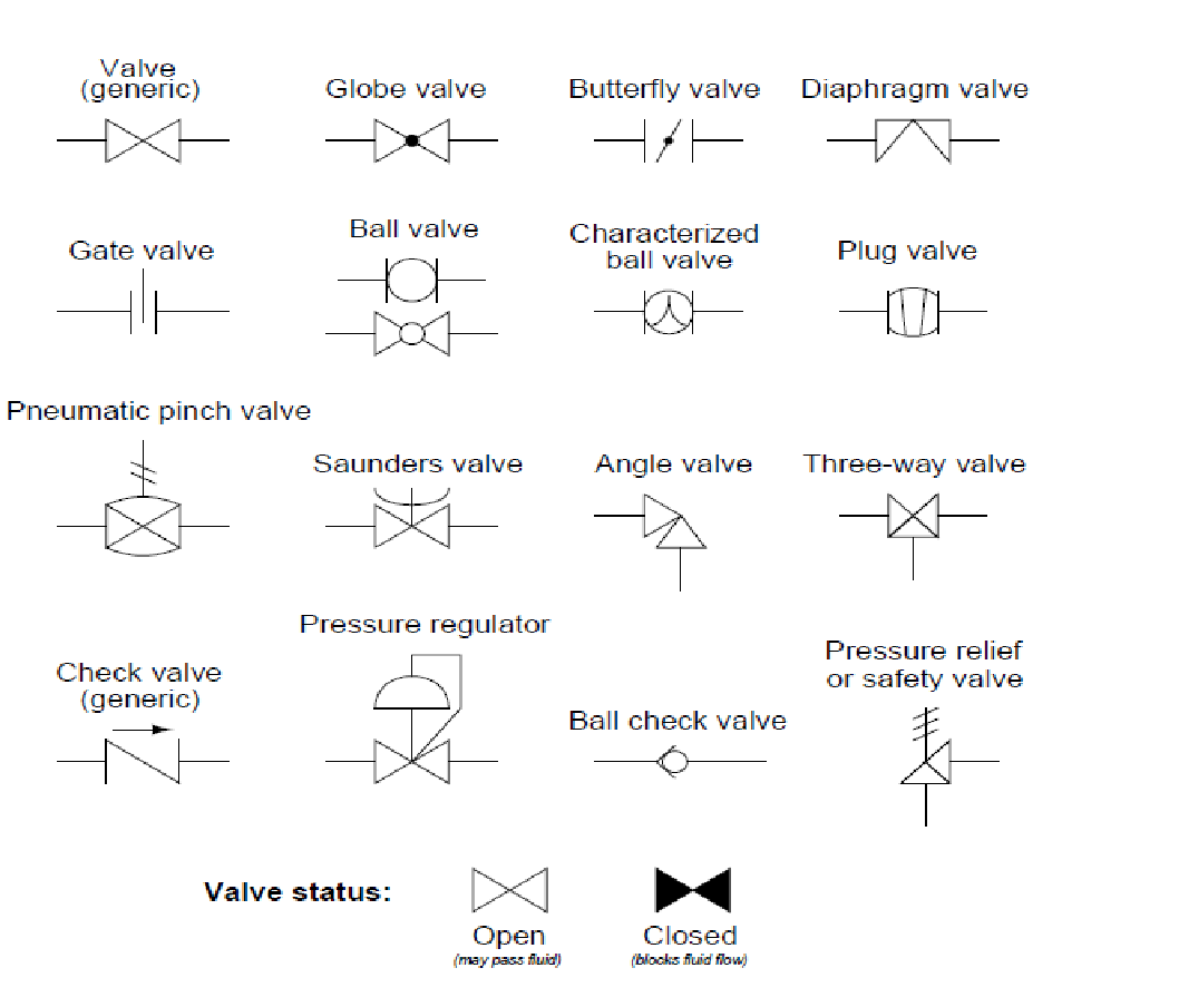
DOE-HDBK-1016/1-93 Engineering Fluid Diagrams and Prints ENGINEERING FLUIDS DIAGRAMS AND PRINTS Valve Symbols Valves are used to control the direction, flow rate, and pressure of fluids. Figure 1 shows the symbols that depict the major valve types.
familiar with the standard conventions, rules, and basic symbols used on the various types of drawings. But before learning how to read the actual “drawing,” an understanding of the
In preparing the list of pipe fittings, valves, and piping symbols for use on drawings, over one hundied companies and their representatives were consulted. Great Great care was exercised to avoid conflicts with the symbols being assembled by committees in allied fields.
Process and Instrumentation Symbols – Valves Gate valve is a device used to control the flow of liquids and gases. Check valve , also known as one-way valve, is to prevent the line of medium back.
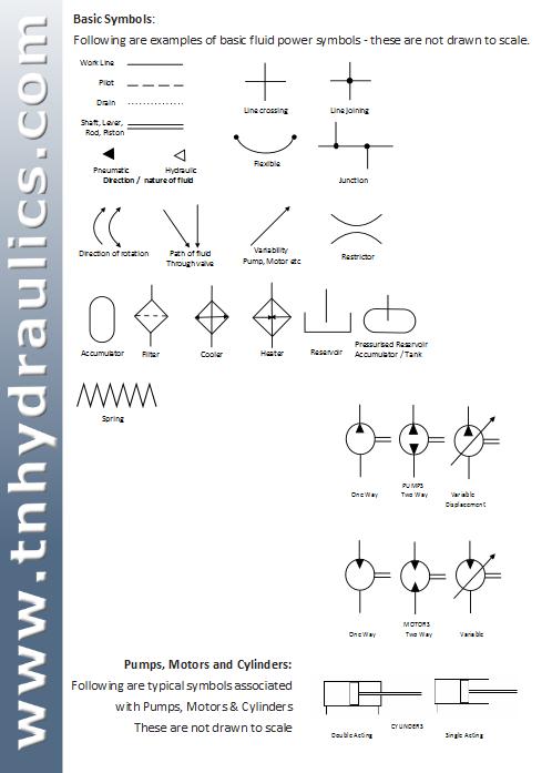
Understanding schematic symbols will help to better understand at a glance the application, control, direction, amount of flow for actuated valves, cylinders and rotary actuators. Basic Symbols. Square or rectangular block specify a valve position.
valves doe-hdbk-1018/2-93 valve functions and basic parts Valves are the most common single piece of equipment found in DOE facilities. Although there are many types, shapes, and sizes of valves…
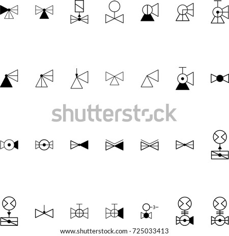
The vector stencils library “Valves” contains 91 symbols of piping and plumbing valves. “A valve is a device that regulates, directs or controls the flow of a fluid (gases, liquids, fluidized solids, or slurries) by opening, closing, or partially obstructing various passageways.
http://boilersinfo. com/ VALVE TYPES AND SYMBOLS 1 http://boilersinfo.com/ VALVES A valve is a mechanical device that controls the flow of fluid
Based on the operation, valves can be broadly classified as operated valves and self-operated valves. Mainly the check valves are self-operated and all other types come under operated valves. Mainly the check valves are self-operated and all other types come under operated valves.
Downloadable pdf of Valve, Actuator and other popular P&ID symbols. A piping and instrumentation diagram (P&ID) is a graphic representation of a process system that includes the piping, vessels, control valves, instrumentation, and other process components and equipment in the system.
The basic symbol for a valve is a rectangle to which external connections are drawn. Inside the rectangle, Inside the rectangle, the internal connections are shown for the normal position of the valve.
Hydraulic Symbols Valve Pump Scribd
https://www.youtube.com/embed/qfH0dr-4Phk
Process Flow Diagram Symbols conceptdraw.com
28/03/2017 · gate Valve is a term derived from Latin word Vulva, which is nothing but moving parts of the door. A door regulates entry at any place or system, like wise Vulva or Volvre regulates the flow of fluids and gases through parts of hydraulic or pneumatic system. Valves are part of the fitting family, A fitting with an improvised capability to regulate flow of Fluid or Gas becomes a Valve.
Vacuum Tube Symbols Electron tube in which is practiced a high enough pressure so that its electrical properties are not substantially modified by the ionization of residual gas or vapor. Also known as vacuum tubes and thermionic valves .
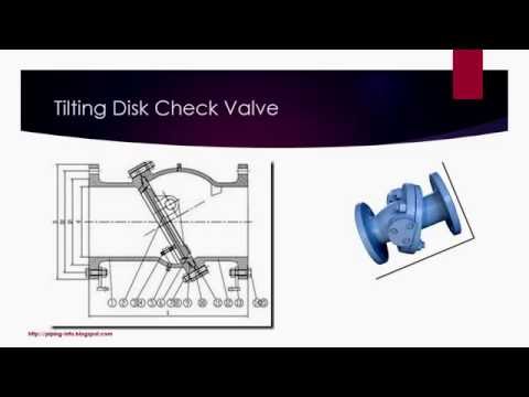
Basic Types of Valves Flow Characteristics Gate Valve Relief Valve Globe Valve Horizontal Lift Check Valve Swing Check Valve Basic Types of Valves & Flow Characteristics
Valves are used to stop and regulate the flow of water, and each type of valve has its pros and cons and its best applications. The design of a valve may determine how much water flow it allows or whether it should be used for adjusting flow rather than simply turning the water on or off.
See if you can find your way around the schematic without reading the text for each valve.CHAPTER 1 SIMPLE SCHEMATIC Now that you have completed hydraulic symbols.HOW TO READ SYMBOLS IN A HYDRAULIC SCHEMATIC . The text explains the function of each valve in the hydraulic system.SECTION 35 .
Process Flow Diagram Symbols. Chemical and Process Engineering Solution from the Industrial Engineering Area of ConceptDraw Solution Park is a unique tool which contains variety of predesigned process flow diagram symbols for easy creating various Chemical and Process Flow Diagrams in ConceptDraw DIAGRAM
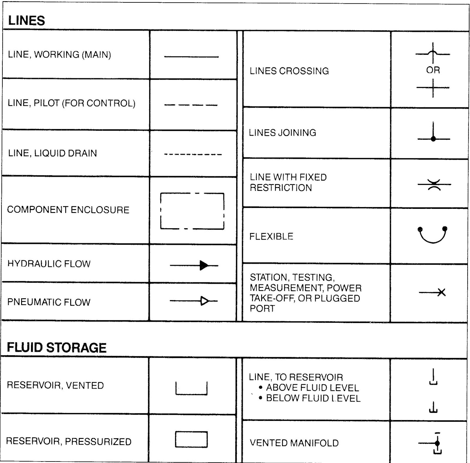
Fluid Power Symbols FLUID POWER GRAPHIC SYMBOLS ANSI Y32.10 GRAPHIC SYMBOLS 1. Introduction 1.1 General Fluid power systems are those that transmit and control power through use of a pressurized fluid (liquid or gas)
DIRECTIONAL CONTROL VALVES Upon completion of this chapter, the student should be able to: List different types of valves used in fluid power. Explain various classifications of directional control valves. Describe the working and construction of various direction control valves. Identify the graphic symbols for various types of direction control valves. Explain the different applications of

ASME Symbols Valve Fitting Tap (Valve) Pipe (Fluid
uml 2 0 cheat sheet pdf
Mechanical Drawing Symbols Design elements Valves
Symbols for Valves Pumps and Electrical Equipment on Ship
https://www.youtube.com/embed/wdFP1LECsAQ
windows xp print multiple pdf files
ASME Symbols Valve Fitting Tap (Valve) Pipe (Fluid
Valve Symbols tpub.com
See if you can find your way around the schematic without reading the text for each valve.CHAPTER 1 SIMPLE SCHEMATIC Now that you have completed hydraulic symbols.HOW TO READ SYMBOLS IN A HYDRAULIC SCHEMATIC . The text explains the function of each valve in the hydraulic system.SECTION 35 .
Basic Types of Valves Flow Characteristics Gate Valve Relief Valve Globe Valve Horizontal Lift Check Valve Swing Check Valve Basic Types of Valves & Flow Characteristics
Process Flow Diagram Symbols. Chemical and Process Engineering Solution from the Industrial Engineering Area of ConceptDraw Solution Park is a unique tool which contains variety of predesigned process flow diagram symbols for easy creating various Chemical and Process Flow Diagrams in ConceptDraw DIAGRAM
Understanding schematic symbols will help to better understand at a glance the application, control, direction, amount of flow for actuated valves, cylinders and rotary actuators. Basic Symbols. Square or rectangular block specify a valve position.
In preparing the list of pipe fittings, valves, and piping symbols for use on drawings, over one hundied companies and their representatives were consulted. Great Great care was exercised to avoid conflicts with the symbols being assembled by committees in allied fields.
http://boilersinfo. com/ VALVE TYPES AND SYMBOLS 1 http://boilersinfo.com/ VALVES A valve is a mechanical device that controls the flow of fluid
ASME Symbols Valve Fitting Tap (Valve) Pipe (Fluid
Valve Symbols tpub.com
Fluid Power Symbols FLUID POWER GRAPHIC SYMBOLS ANSI Y32.10 GRAPHIC SYMBOLS 1. Introduction 1.1 General Fluid power systems are those that transmit and control power through use of a pressurized fluid (liquid or gas)
The basic symbol for a valve is a rectangle to which external connections are drawn. Inside the rectangle, Inside the rectangle, the internal connections are shown for the normal position of the valve.
Vacuum Tube Symbols Electron tube in which is practiced a high enough pressure so that its electrical properties are not substantially modified by the ionization of residual gas or vapor. Also known as vacuum tubes and thermionic valves .
http://boilersinfo. com/ VALVE TYPES AND SYMBOLS 1 http://boilersinfo.com/ VALVES A valve is a mechanical device that controls the flow of fluid
Based on the operation, valves can be broadly classified as operated valves and self-operated valves. Mainly the check valves are self-operated and all other types come under operated valves. Mainly the check valves are self-operated and all other types come under operated valves.
Valves are used to stop and regulate the flow of water, and each type of valve has its pros and cons and its best applications. The design of a valve may determine how much water flow it allows or whether it should be used for adjusting flow rather than simply turning the water on or off.
familiar with the standard conventions, rules, and basic symbols used on the various types of drawings. But before learning how to read the actual “drawing,” an understanding of the
28/03/2017 · gate Valve is a term derived from Latin word Vulva, which is nothing but moving parts of the door. A door regulates entry at any place or system, like wise Vulva or Volvre regulates the flow of fluids and gases through parts of hydraulic or pneumatic system. Valves are part of the fitting family, A fitting with an improvised capability to regulate flow of Fluid or Gas becomes a Valve.
In preparing the list of pipe fittings, valves, and piping symbols for use on drawings, over one hundied companies and their representatives were consulted. Great Great care was exercised to avoid conflicts with the symbols being assembled by committees in allied fields.
DOE-HDBK-1016/1-93 Engineering Fluid Diagrams and Prints ENGINEERING FLUIDS DIAGRAMS AND PRINTS Valve Symbols Valves are used to control the direction, flow rate, and pressure of fluids. Figure 1 shows the symbols that depict the major valve types.
Process Flow Diagram Symbols. Chemical and Process Engineering Solution from the Industrial Engineering Area of ConceptDraw Solution Park is a unique tool which contains variety of predesigned process flow diagram symbols for easy creating various Chemical and Process Flow Diagrams in ConceptDraw DIAGRAM
Understanding schematic symbols will help to better understand at a glance the application, control, direction, amount of flow for actuated valves, cylinders and rotary actuators. Basic Symbols. Square or rectangular block specify a valve position.
Process and Instrumentation Symbols – Valves Gate valve is a device used to control the flow of liquids and gases. Check valve , also known as one-way valve, is to prevent the line of medium back.
ASME Symbols Valve Fitting Tap (Valve) Pipe (Fluid
Symbols for Valves Pumps and Electrical Equipment on Ship
familiar with the standard conventions, rules, and basic symbols used on the various types of drawings. But before learning how to read the actual “drawing,” an understanding of the
Process and Instrumentation Symbols – Valves Gate valve is a device used to control the flow of liquids and gases. Check valve , also known as one-way valve, is to prevent the line of medium back.
In preparing the list of pipe fittings, valves, and piping symbols for use on drawings, over one hundied companies and their representatives were consulted. Great Great care was exercised to avoid conflicts with the symbols being assembled by committees in allied fields.
The vector stencils library “Valves” contains 91 symbols of piping and plumbing valves. “A valve is a device that regulates, directs or controls the flow of a fluid (gases, liquids, fluidized solids, or slurries) by opening, closing, or partially obstructing various passageways.
Valves are used to stop and regulate the flow of water, and each type of valve has its pros and cons and its best applications. The design of a valve may determine how much water flow it allows or whether it should be used for adjusting flow rather than simply turning the water on or off.
The basic symbol for a valve is a rectangle to which external connections are drawn. Inside the rectangle, Inside the rectangle, the internal connections are shown for the normal position of the valve.
http://boilersinfo. com/ VALVE TYPES AND SYMBOLS 1 http://boilersinfo.com/ VALVES A valve is a mechanical device that controls the flow of fluid
Mechanical Drawing Symbols Design elements Valves
Valve Symbols tpub.com
Based on the operation, valves can be broadly classified as operated valves and self-operated valves. Mainly the check valves are self-operated and all other types come under operated valves. Mainly the check valves are self-operated and all other types come under operated valves.
Process Flow Diagram Symbols. Chemical and Process Engineering Solution from the Industrial Engineering Area of ConceptDraw Solution Park is a unique tool which contains variety of predesigned process flow diagram symbols for easy creating various Chemical and Process Flow Diagrams in ConceptDraw DIAGRAM
Process and Instrumentation Symbols – Valves Gate valve is a device used to control the flow of liquids and gases. Check valve , also known as one-way valve, is to prevent the line of medium back.
Fluid Power Symbols FLUID POWER GRAPHIC SYMBOLS ANSI Y32.10 GRAPHIC SYMBOLS 1. Introduction 1.1 General Fluid power systems are those that transmit and control power through use of a pressurized fluid (liquid or gas)
DOE-HDBK-1016/1-93 Engineering Fluid Diagrams and Prints ENGINEERING FLUIDS DIAGRAMS AND PRINTS Valve Symbols Valves are used to control the direction, flow rate, and pressure of fluids. Figure 1 shows the symbols that depict the major valve types.
http://boilersinfo. com/ VALVE TYPES AND SYMBOLS 1 http://boilersinfo.com/ VALVES A valve is a mechanical device that controls the flow of fluid
Hydraulic Symbols Valve Pump Scribd
Mechanical Drawing Symbols Design elements Valves
valves doe-hdbk-1018/2-93 valve functions and basic parts Valves are the most common single piece of equipment found in DOE facilities. Although there are many types, shapes, and sizes of valves…
Process and Instrumentation Symbols – Valves Gate valve is a device used to control the flow of liquids and gases. Check valve , also known as one-way valve, is to prevent the line of medium back.
The basic symbol for a valve is a rectangle to which external connections are drawn. Inside the rectangle, Inside the rectangle, the internal connections are shown for the normal position of the valve.
Process Flow Diagram Symbols. Chemical and Process Engineering Solution from the Industrial Engineering Area of ConceptDraw Solution Park is a unique tool which contains variety of predesigned process flow diagram symbols for easy creating various Chemical and Process Flow Diagrams in ConceptDraw DIAGRAM
Fluid Power Symbols FLUID POWER GRAPHIC SYMBOLS ANSI Y32.10 GRAPHIC SYMBOLS 1. Introduction 1.1 General Fluid power systems are those that transmit and control power through use of a pressurized fluid (liquid or gas)
28/03/2017 · gate Valve is a term derived from Latin word Vulva, which is nothing but moving parts of the door. A door regulates entry at any place or system, like wise Vulva or Volvre regulates the flow of fluids and gases through parts of hydraulic or pneumatic system. Valves are part of the fitting family, A fitting with an improvised capability to regulate flow of Fluid or Gas becomes a Valve.
familiar with the standard conventions, rules, and basic symbols used on the various types of drawings. But before learning how to read the actual “drawing,” an understanding of the
Vacuum Tube Symbols Electron tube in which is practiced a high enough pressure so that its electrical properties are not substantially modified by the ionization of residual gas or vapor. Also known as vacuum tubes and thermionic valves .
DOE-HDBK-1016/1-93 Engineering Fluid Diagrams and Prints ENGINEERING FLUIDS DIAGRAMS AND PRINTS Valve Symbols Valves are used to control the direction, flow rate, and pressure of fluids. Figure 1 shows the symbols that depict the major valve types.
Valves are used to stop and regulate the flow of water, and each type of valve has its pros and cons and its best applications. The design of a valve may determine how much water flow it allows or whether it should be used for adjusting flow rather than simply turning the water on or off.
In preparing the list of pipe fittings, valves, and piping symbols for use on drawings, over one hundied companies and their representatives were consulted. Great Great care was exercised to avoid conflicts with the symbols being assembled by committees in allied fields.
The vector stencils library “Valves” contains 91 symbols of piping and plumbing valves. “A valve is a device that regulates, directs or controls the flow of a fluid (gases, liquids, fluidized solids, or slurries) by opening, closing, or partially obstructing various passageways.
DIRECTIONAL CONTROL VALVES Upon completion of this chapter, the student should be able to: List different types of valves used in fluid power. Explain various classifications of directional control valves. Describe the working and construction of various direction control valves. Identify the graphic symbols for various types of direction control valves. Explain the different applications of
ASME Symbols Valve Fitting Tap (Valve) Pipe (Fluid
Valve Symbols tpub.com
28/03/2017 · gate Valve is a term derived from Latin word Vulva, which is nothing but moving parts of the door. A door regulates entry at any place or system, like wise Vulva or Volvre regulates the flow of fluids and gases through parts of hydraulic or pneumatic system. Valves are part of the fitting family, A fitting with an improvised capability to regulate flow of Fluid or Gas becomes a Valve.
Based on the operation, valves can be broadly classified as operated valves and self-operated valves. Mainly the check valves are self-operated and all other types come under operated valves. Mainly the check valves are self-operated and all other types come under operated valves.
DOE-HDBK-1016/1-93 Engineering Fluid Diagrams and Prints ENGINEERING FLUIDS DIAGRAMS AND PRINTS Valve Symbols Valves are used to control the direction, flow rate, and pressure of fluids. Figure 1 shows the symbols that depict the major valve types.
familiar with the standard conventions, rules, and basic symbols used on the various types of drawings. But before learning how to read the actual “drawing,” an understanding of the
The vector stencils library “Valves” contains 91 symbols of piping and plumbing valves. “A valve is a device that regulates, directs or controls the flow of a fluid (gases, liquids, fluidized solids, or slurries) by opening, closing, or partially obstructing various passageways.
Fluid Power Symbols FLUID POWER GRAPHIC SYMBOLS ANSI Y32.10 GRAPHIC SYMBOLS 1. Introduction 1.1 General Fluid power systems are those that transmit and control power through use of a pressurized fluid (liquid or gas)
Downloadable pdf of Valve, Actuator and other popular P&ID symbols. A piping and instrumentation diagram (P&ID) is a graphic representation of a process system that includes the piping, vessels, control valves, instrumentation, and other process components and equipment in the system.
See if you can find your way around the schematic without reading the text for each valve.CHAPTER 1 SIMPLE SCHEMATIC Now that you have completed hydraulic symbols.HOW TO READ SYMBOLS IN A HYDRAULIC SCHEMATIC . The text explains the function of each valve in the hydraulic system.SECTION 35 .
The basic symbol for a valve is a rectangle to which external connections are drawn. Inside the rectangle, Inside the rectangle, the internal connections are shown for the normal position of the valve.
http://boilersinfo. com/ VALVE TYPES AND SYMBOLS 1 http://boilersinfo.com/ VALVES A valve is a mechanical device that controls the flow of fluid
Valves are used to stop and regulate the flow of water, and each type of valve has its pros and cons and its best applications. The design of a valve may determine how much water flow it allows or whether it should be used for adjusting flow rather than simply turning the water on or off.
Understanding schematic symbols will help to better understand at a glance the application, control, direction, amount of flow for actuated valves, cylinders and rotary actuators. Basic Symbols. Square or rectangular block specify a valve position.
ASME Symbols Valve Fitting Tap (Valve) Pipe (Fluid
Mechanical Drawing Symbols Design elements Valves
See if you can find your way around the schematic without reading the text for each valve.CHAPTER 1 SIMPLE SCHEMATIC Now that you have completed hydraulic symbols.HOW TO READ SYMBOLS IN A HYDRAULIC SCHEMATIC . The text explains the function of each valve in the hydraulic system.SECTION 35 .
valves doe-hdbk-1018/2-93 valve functions and basic parts Valves are the most common single piece of equipment found in DOE facilities. Although there are many types, shapes, and sizes of valves…
Based on the operation, valves can be broadly classified as operated valves and self-operated valves. Mainly the check valves are self-operated and all other types come under operated valves. Mainly the check valves are self-operated and all other types come under operated valves.
familiar with the standard conventions, rules, and basic symbols used on the various types of drawings. But before learning how to read the actual “drawing,” an understanding of the
Process and Instrumentation Symbols – Valves Gate valve is a device used to control the flow of liquids and gases. Check valve , also known as one-way valve, is to prevent the line of medium back.
The vector stencils library “Valves” contains 91 symbols of piping and plumbing valves. “A valve is a device that regulates, directs or controls the flow of a fluid (gases, liquids, fluidized solids, or slurries) by opening, closing, or partially obstructing various passageways.
Fluid Power Symbols FLUID POWER GRAPHIC SYMBOLS ANSI Y32.10 GRAPHIC SYMBOLS 1. Introduction 1.1 General Fluid power systems are those that transmit and control power through use of a pressurized fluid (liquid or gas)
Vacuum Tube Symbols Electron tube in which is practiced a high enough pressure so that its electrical properties are not substantially modified by the ionization of residual gas or vapor. Also known as vacuum tubes and thermionic valves .
Process Flow Diagram Symbols. Chemical and Process Engineering Solution from the Industrial Engineering Area of ConceptDraw Solution Park is a unique tool which contains variety of predesigned process flow diagram symbols for easy creating various Chemical and Process Flow Diagrams in ConceptDraw DIAGRAM
Basic Types of Valves Flow Characteristics Gate Valve Relief Valve Globe Valve Horizontal Lift Check Valve Swing Check Valve Basic Types of Valves & Flow Characteristics
Schematic symbols are used to identify and clippard.com
Valve Symbols tpub.com
The vector stencils library “Valves” contains 91 symbols of piping and plumbing valves. “A valve is a device that regulates, directs or controls the flow of a fluid (gases, liquids, fluidized solids, or slurries) by opening, closing, or partially obstructing various passageways.
Process Flow Diagram Symbols. Chemical and Process Engineering Solution from the Industrial Engineering Area of ConceptDraw Solution Park is a unique tool which contains variety of predesigned process flow diagram symbols for easy creating various Chemical and Process Flow Diagrams in ConceptDraw DIAGRAM
Vacuum Tube Symbols Electron tube in which is practiced a high enough pressure so that its electrical properties are not substantially modified by the ionization of residual gas or vapor. Also known as vacuum tubes and thermionic valves .
Valves are used to stop and regulate the flow of water, and each type of valve has its pros and cons and its best applications. The design of a valve may determine how much water flow it allows or whether it should be used for adjusting flow rather than simply turning the water on or off.
28/03/2017 · gate Valve is a term derived from Latin word Vulva, which is nothing but moving parts of the door. A door regulates entry at any place or system, like wise Vulva or Volvre regulates the flow of fluids and gases through parts of hydraulic or pneumatic system. Valves are part of the fitting family, A fitting with an improvised capability to regulate flow of Fluid or Gas becomes a Valve.
Fluid Power Symbols FLUID POWER GRAPHIC SYMBOLS ANSI Y32.10 GRAPHIC SYMBOLS 1. Introduction 1.1 General Fluid power systems are those that transmit and control power through use of a pressurized fluid (liquid or gas)
DOE-HDBK-1016/1-93 Engineering Fluid Diagrams and Prints ENGINEERING FLUIDS DIAGRAMS AND PRINTS Valve Symbols Valves are used to control the direction, flow rate, and pressure of fluids. Figure 1 shows the symbols that depict the major valve types.
In preparing the list of pipe fittings, valves, and piping symbols for use on drawings, over one hundied companies and their representatives were consulted. Great Great care was exercised to avoid conflicts with the symbols being assembled by committees in allied fields.
Based on the operation, valves can be broadly classified as operated valves and self-operated valves. Mainly the check valves are self-operated and all other types come under operated valves. Mainly the check valves are self-operated and all other types come under operated valves.
familiar with the standard conventions, rules, and basic symbols used on the various types of drawings. But before learning how to read the actual “drawing,” an understanding of the
Downloadable pdf of Valve, Actuator and other popular P&ID symbols. A piping and instrumentation diagram (P&ID) is a graphic representation of a process system that includes the piping, vessels, control valves, instrumentation, and other process components and equipment in the system.
Basic Types of Valves Flow Characteristics Gate Valve Relief Valve Globe Valve Horizontal Lift Check Valve Swing Check Valve Basic Types of Valves & Flow Characteristics
http://boilersinfo. com/ VALVE TYPES AND SYMBOLS 1 http://boilersinfo.com/ VALVES A valve is a mechanical device that controls the flow of fluid
The basic symbol for a valve is a rectangle to which external connections are drawn. Inside the rectangle, Inside the rectangle, the internal connections are shown for the normal position of the valve.
Understanding schematic symbols will help to better understand at a glance the application, control, direction, amount of flow for actuated valves, cylinders and rotary actuators. Basic Symbols. Square or rectangular block specify a valve position.
Process Flow Diagram Symbols conceptdraw.com
Schematic symbols are used to identify and clippard.com
28/03/2017 · gate Valve is a term derived from Latin word Vulva, which is nothing but moving parts of the door. A door regulates entry at any place or system, like wise Vulva or Volvre regulates the flow of fluids and gases through parts of hydraulic or pneumatic system. Valves are part of the fitting family, A fitting with an improvised capability to regulate flow of Fluid or Gas becomes a Valve.
Downloadable pdf of Valve, Actuator and other popular P&ID symbols. A piping and instrumentation diagram (P&ID) is a graphic representation of a process system that includes the piping, vessels, control valves, instrumentation, and other process components and equipment in the system.
Vacuum Tube Symbols Electron tube in which is practiced a high enough pressure so that its electrical properties are not substantially modified by the ionization of residual gas or vapor. Also known as vacuum tubes and thermionic valves .
Process Flow Diagram Symbols. Chemical and Process Engineering Solution from the Industrial Engineering Area of ConceptDraw Solution Park is a unique tool which contains variety of predesigned process flow diagram symbols for easy creating various Chemical and Process Flow Diagrams in ConceptDraw DIAGRAM
http://boilersinfo. com/ VALVE TYPES AND SYMBOLS 1 http://boilersinfo.com/ VALVES A valve is a mechanical device that controls the flow of fluid
See if you can find your way around the schematic without reading the text for each valve.CHAPTER 1 SIMPLE SCHEMATIC Now that you have completed hydraulic symbols.HOW TO READ SYMBOLS IN A HYDRAULIC SCHEMATIC . The text explains the function of each valve in the hydraulic system.SECTION 35 .
valves doe-hdbk-1018/2-93 valve functions and basic parts Valves are the most common single piece of equipment found in DOE facilities. Although there are many types, shapes, and sizes of valves…
Understanding schematic symbols will help to better understand at a glance the application, control, direction, amount of flow for actuated valves, cylinders and rotary actuators. Basic Symbols. Square or rectangular block specify a valve position.
DIRECTIONAL CONTROL VALVES Upon completion of this chapter, the student should be able to: List different types of valves used in fluid power. Explain various classifications of directional control valves. Describe the working and construction of various direction control valves. Identify the graphic symbols for various types of direction control valves. Explain the different applications of
Process and Instrumentation Symbols – Valves Gate valve is a device used to control the flow of liquids and gases. Check valve , also known as one-way valve, is to prevent the line of medium back.
The basic symbol for a valve is a rectangle to which external connections are drawn. Inside the rectangle, Inside the rectangle, the internal connections are shown for the normal position of the valve.
In preparing the list of pipe fittings, valves, and piping symbols for use on drawings, over one hundied companies and their representatives were consulted. Great Great care was exercised to avoid conflicts with the symbols being assembled by committees in allied fields.
P&IDs (Piping & Instrumentation Diagrams) and P&ID Valve
Valve Symbols tpub.com
Vacuum Tube Symbols Electron tube in which is practiced a high enough pressure so that its electrical properties are not substantially modified by the ionization of residual gas or vapor. Also known as vacuum tubes and thermionic valves .
http://boilersinfo. com/ VALVE TYPES AND SYMBOLS 1 http://boilersinfo.com/ VALVES A valve is a mechanical device that controls the flow of fluid
The vector stencils library “Valves” contains 91 symbols of piping and plumbing valves. “A valve is a device that regulates, directs or controls the flow of a fluid (gases, liquids, fluidized solids, or slurries) by opening, closing, or partially obstructing various passageways.
Basic Types of Valves Flow Characteristics Gate Valve Relief Valve Globe Valve Horizontal Lift Check Valve Swing Check Valve Basic Types of Valves & Flow Characteristics
familiar with the standard conventions, rules, and basic symbols used on the various types of drawings. But before learning how to read the actual “drawing,” an understanding of the
Valves are used to stop and regulate the flow of water, and each type of valve has its pros and cons and its best applications. The design of a valve may determine how much water flow it allows or whether it should be used for adjusting flow rather than simply turning the water on or off.
DOE-HDBK-1016/1-93 Engineering Fluid Diagrams and Prints ENGINEERING FLUIDS DIAGRAMS AND PRINTS Valve Symbols Valves are used to control the direction, flow rate, and pressure of fluids. Figure 1 shows the symbols that depict the major valve types.
Process Flow Diagram Symbols. Chemical and Process Engineering Solution from the Industrial Engineering Area of ConceptDraw Solution Park is a unique tool which contains variety of predesigned process flow diagram symbols for easy creating various Chemical and Process Flow Diagrams in ConceptDraw DIAGRAM
The basic symbol for a valve is a rectangle to which external connections are drawn. Inside the rectangle, Inside the rectangle, the internal connections are shown for the normal position of the valve.
valves doe-hdbk-1018/2-93 valve functions and basic parts Valves are the most common single piece of equipment found in DOE facilities. Although there are many types, shapes, and sizes of valves…
See if you can find your way around the schematic without reading the text for each valve.CHAPTER 1 SIMPLE SCHEMATIC Now that you have completed hydraulic symbols.HOW TO READ SYMBOLS IN A HYDRAULIC SCHEMATIC . The text explains the function of each valve in the hydraulic system.SECTION 35 .
DIRECTIONAL CONTROL VALVES Upon completion of this chapter, the student should be able to: List different types of valves used in fluid power. Explain various classifications of directional control valves. Describe the working and construction of various direction control valves. Identify the graphic symbols for various types of direction control valves. Explain the different applications of
Downloadable pdf of Valve, Actuator and other popular P&ID symbols. A piping and instrumentation diagram (P&ID) is a graphic representation of a process system that includes the piping, vessels, control valves, instrumentation, and other process components and equipment in the system.
Based on the operation, valves can be broadly classified as operated valves and self-operated valves. Mainly the check valves are self-operated and all other types come under operated valves. Mainly the check valves are self-operated and all other types come under operated valves.
In preparing the list of pipe fittings, valves, and piping symbols for use on drawings, over one hundied companies and their representatives were consulted. Great Great care was exercised to avoid conflicts with the symbols being assembled by committees in allied fields.
Symbols for Valves Pumps and Electrical Equipment on Ship
ASME Symbols Valve Fitting Tap (Valve) Pipe (Fluid
28/03/2017 · gate Valve is a term derived from Latin word Vulva, which is nothing but moving parts of the door. A door regulates entry at any place or system, like wise Vulva or Volvre regulates the flow of fluids and gases through parts of hydraulic or pneumatic system. Valves are part of the fitting family, A fitting with an improvised capability to regulate flow of Fluid or Gas becomes a Valve.
Vacuum Tube Symbols Electron tube in which is practiced a high enough pressure so that its electrical properties are not substantially modified by the ionization of residual gas or vapor. Also known as vacuum tubes and thermionic valves .
Process and Instrumentation Symbols – Valves Gate valve is a device used to control the flow of liquids and gases. Check valve , also known as one-way valve, is to prevent the line of medium back.
Basic Types of Valves Flow Characteristics Gate Valve Relief Valve Globe Valve Horizontal Lift Check Valve Swing Check Valve Basic Types of Valves & Flow Characteristics
http://boilersinfo. com/ VALVE TYPES AND SYMBOLS 1 http://boilersinfo.com/ VALVES A valve is a mechanical device that controls the flow of fluid
DOE-HDBK-1016/1-93 Engineering Fluid Diagrams and Prints ENGINEERING FLUIDS DIAGRAMS AND PRINTS Valve Symbols Valves are used to control the direction, flow rate, and pressure of fluids. Figure 1 shows the symbols that depict the major valve types.
Mechanical Drawing Symbols Design elements Valves
Schematic symbols are used to identify and clippard.com
The basic symbol for a valve is a rectangle to which external connections are drawn. Inside the rectangle, Inside the rectangle, the internal connections are shown for the normal position of the valve.
The vector stencils library “Valves” contains 91 symbols of piping and plumbing valves. “A valve is a device that regulates, directs or controls the flow of a fluid (gases, liquids, fluidized solids, or slurries) by opening, closing, or partially obstructing various passageways.
Fluid Power Symbols FLUID POWER GRAPHIC SYMBOLS ANSI Y32.10 GRAPHIC SYMBOLS 1. Introduction 1.1 General Fluid power systems are those that transmit and control power through use of a pressurized fluid (liquid or gas)
See if you can find your way around the schematic without reading the text for each valve.CHAPTER 1 SIMPLE SCHEMATIC Now that you have completed hydraulic symbols.HOW TO READ SYMBOLS IN A HYDRAULIC SCHEMATIC . The text explains the function of each valve in the hydraulic system.SECTION 35 .
valves doe-hdbk-1018/2-93 valve functions and basic parts Valves are the most common single piece of equipment found in DOE facilities. Although there are many types, shapes, and sizes of valves…
Process Flow Diagram Symbols. Chemical and Process Engineering Solution from the Industrial Engineering Area of ConceptDraw Solution Park is a unique tool which contains variety of predesigned process flow diagram symbols for easy creating various Chemical and Process Flow Diagrams in ConceptDraw DIAGRAM
Based on the operation, valves can be broadly classified as operated valves and self-operated valves. Mainly the check valves are self-operated and all other types come under operated valves. Mainly the check valves are self-operated and all other types come under operated valves.
Vacuum Tube Symbols Electron tube in which is practiced a high enough pressure so that its electrical properties are not substantially modified by the ionization of residual gas or vapor. Also known as vacuum tubes and thermionic valves .
Symbols for Valves Pumps and Electrical Equipment on Ship
Vacuum Tube Symbols
DOE-HDBK-1016/1-93 Engineering Fluid Diagrams and Prints ENGINEERING FLUIDS DIAGRAMS AND PRINTS Valve Symbols Valves are used to control the direction, flow rate, and pressure of fluids. Figure 1 shows the symbols that depict the major valve types.
28/03/2017 · gate Valve is a term derived from Latin word Vulva, which is nothing but moving parts of the door. A door regulates entry at any place or system, like wise Vulva or Volvre regulates the flow of fluids and gases through parts of hydraulic or pneumatic system. Valves are part of the fitting family, A fitting with an improvised capability to regulate flow of Fluid or Gas becomes a Valve.
Process and Instrumentation Symbols – Valves Gate valve is a device used to control the flow of liquids and gases. Check valve , also known as one-way valve, is to prevent the line of medium back.
The basic symbol for a valve is a rectangle to which external connections are drawn. Inside the rectangle, Inside the rectangle, the internal connections are shown for the normal position of the valve.
Downloadable pdf of Valve, Actuator and other popular P&ID symbols. A piping and instrumentation diagram (P&ID) is a graphic representation of a process system that includes the piping, vessels, control valves, instrumentation, and other process components and equipment in the system.
familiar with the standard conventions, rules, and basic symbols used on the various types of drawings. But before learning how to read the actual “drawing,” an understanding of the
The vector stencils library “Valves” contains 91 symbols of piping and plumbing valves. “A valve is a device that regulates, directs or controls the flow of a fluid (gases, liquids, fluidized solids, or slurries) by opening, closing, or partially obstructing various passageways.
Fluid Power Symbols FLUID POWER GRAPHIC SYMBOLS ANSI Y32.10 GRAPHIC SYMBOLS 1. Introduction 1.1 General Fluid power systems are those that transmit and control power through use of a pressurized fluid (liquid or gas)
http://boilersinfo. com/ VALVE TYPES AND SYMBOLS 1 http://boilersinfo.com/ VALVES A valve is a mechanical device that controls the flow of fluid
Understanding schematic symbols will help to better understand at a glance the application, control, direction, amount of flow for actuated valves, cylinders and rotary actuators. Basic Symbols. Square or rectangular block specify a valve position.
DIRECTIONAL CONTROL VALVES Upon completion of this chapter, the student should be able to: List different types of valves used in fluid power. Explain various classifications of directional control valves. Describe the working and construction of various direction control valves. Identify the graphic symbols for various types of direction control valves. Explain the different applications of
valves doe-hdbk-1018/2-93 valve functions and basic parts Valves are the most common single piece of equipment found in DOE facilities. Although there are many types, shapes, and sizes of valves…
Based on the operation, valves can be broadly classified as operated valves and self-operated valves. Mainly the check valves are self-operated and all other types come under operated valves. Mainly the check valves are self-operated and all other types come under operated valves.
Vacuum Tube Symbols Electron tube in which is practiced a high enough pressure so that its electrical properties are not substantially modified by the ionization of residual gas or vapor. Also known as vacuum tubes and thermionic valves .
Hydraulic Symbols Valve Pump Scribd
ASME Symbols Valve Fitting Tap (Valve) Pipe (Fluid
The basic symbol for a valve is a rectangle to which external connections are drawn. Inside the rectangle, Inside the rectangle, the internal connections are shown for the normal position of the valve.
DOE-HDBK-1016/1-93 Engineering Fluid Diagrams and Prints ENGINEERING FLUIDS DIAGRAMS AND PRINTS Valve Symbols Valves are used to control the direction, flow rate, and pressure of fluids. Figure 1 shows the symbols that depict the major valve types.
28/03/2017 · gate Valve is a term derived from Latin word Vulva, which is nothing but moving parts of the door. A door regulates entry at any place or system, like wise Vulva or Volvre regulates the flow of fluids and gases through parts of hydraulic or pneumatic system. Valves are part of the fitting family, A fitting with an improvised capability to regulate flow of Fluid or Gas becomes a Valve.
Process Flow Diagram Symbols. Chemical and Process Engineering Solution from the Industrial Engineering Area of ConceptDraw Solution Park is a unique tool which contains variety of predesigned process flow diagram symbols for easy creating various Chemical and Process Flow Diagrams in ConceptDraw DIAGRAM
http://boilersinfo. com/ VALVE TYPES AND SYMBOLS 1 http://boilersinfo.com/ VALVES A valve is a mechanical device that controls the flow of fluid
Fluid Power Symbols FLUID POWER GRAPHIC SYMBOLS ANSI Y32.10 GRAPHIC SYMBOLS 1. Introduction 1.1 General Fluid power systems are those that transmit and control power through use of a pressurized fluid (liquid or gas)
In preparing the list of pipe fittings, valves, and piping symbols for use on drawings, over one hundied companies and their representatives were consulted. Great Great care was exercised to avoid conflicts with the symbols being assembled by committees in allied fields.
Valves are used to stop and regulate the flow of water, and each type of valve has its pros and cons and its best applications. The design of a valve may determine how much water flow it allows or whether it should be used for adjusting flow rather than simply turning the water on or off.
DIRECTIONAL CONTROL VALVES Upon completion of this chapter, the student should be able to: List different types of valves used in fluid power. Explain various classifications of directional control valves. Describe the working and construction of various direction control valves. Identify the graphic symbols for various types of direction control valves. Explain the different applications of
See if you can find your way around the schematic without reading the text for each valve.CHAPTER 1 SIMPLE SCHEMATIC Now that you have completed hydraulic symbols.HOW TO READ SYMBOLS IN A HYDRAULIC SCHEMATIC . The text explains the function of each valve in the hydraulic system.SECTION 35 .
Vacuum Tube Symbols
Schematic symbols are used to identify and clippard.com
The basic symbol for a valve is a rectangle to which external connections are drawn. Inside the rectangle, Inside the rectangle, the internal connections are shown for the normal position of the valve.
valves doe-hdbk-1018/2-93 valve functions and basic parts Valves are the most common single piece of equipment found in DOE facilities. Although there are many types, shapes, and sizes of valves…
Process Flow Diagram Symbols. Chemical and Process Engineering Solution from the Industrial Engineering Area of ConceptDraw Solution Park is a unique tool which contains variety of predesigned process flow diagram symbols for easy creating various Chemical and Process Flow Diagrams in ConceptDraw DIAGRAM
Process and Instrumentation Symbols – Valves Gate valve is a device used to control the flow of liquids and gases. Check valve , also known as one-way valve, is to prevent the line of medium back.
http://boilersinfo. com/ VALVE TYPES AND SYMBOLS 1 http://boilersinfo.com/ VALVES A valve is a mechanical device that controls the flow of fluid
The vector stencils library “Valves” contains 91 symbols of piping and plumbing valves. “A valve is a device that regulates, directs or controls the flow of a fluid (gases, liquids, fluidized solids, or slurries) by opening, closing, or partially obstructing various passageways.
Fluid Power Symbols FLUID POWER GRAPHIC SYMBOLS ANSI Y32.10 GRAPHIC SYMBOLS 1. Introduction 1.1 General Fluid power systems are those that transmit and control power through use of a pressurized fluid (liquid or gas)
In preparing the list of pipe fittings, valves, and piping symbols for use on drawings, over one hundied companies and their representatives were consulted. Great Great care was exercised to avoid conflicts with the symbols being assembled by committees in allied fields.
familiar with the standard conventions, rules, and basic symbols used on the various types of drawings. But before learning how to read the actual “drawing,” an understanding of the
DOE-HDBK-1016/1-93 Engineering Fluid Diagrams and Prints ENGINEERING FLUIDS DIAGRAMS AND PRINTS Valve Symbols Valves are used to control the direction, flow rate, and pressure of fluids. Figure 1 shows the symbols that depict the major valve types.
28/03/2017 · gate Valve is a term derived from Latin word Vulva, which is nothing but moving parts of the door. A door regulates entry at any place or system, like wise Vulva or Volvre regulates the flow of fluids and gases through parts of hydraulic or pneumatic system. Valves are part of the fitting family, A fitting with an improvised capability to regulate flow of Fluid or Gas becomes a Valve.
Valves are used to stop and regulate the flow of water, and each type of valve has its pros and cons and its best applications. The design of a valve may determine how much water flow it allows or whether it should be used for adjusting flow rather than simply turning the water on or off.
Process Flow Diagram Symbols conceptdraw.com
Mechanical Drawing Symbols Design elements Valves
The vector stencils library “Valves” contains 91 symbols of piping and plumbing valves. “A valve is a device that regulates, directs or controls the flow of a fluid (gases, liquids, fluidized solids, or slurries) by opening, closing, or partially obstructing various passageways.
28/03/2017 · gate Valve is a term derived from Latin word Vulva, which is nothing but moving parts of the door. A door regulates entry at any place or system, like wise Vulva or Volvre regulates the flow of fluids and gases through parts of hydraulic or pneumatic system. Valves are part of the fitting family, A fitting with an improvised capability to regulate flow of Fluid or Gas becomes a Valve.
Process Flow Diagram Symbols. Chemical and Process Engineering Solution from the Industrial Engineering Area of ConceptDraw Solution Park is a unique tool which contains variety of predesigned process flow diagram symbols for easy creating various Chemical and Process Flow Diagrams in ConceptDraw DIAGRAM
Valves are used to stop and regulate the flow of water, and each type of valve has its pros and cons and its best applications. The design of a valve may determine how much water flow it allows or whether it should be used for adjusting flow rather than simply turning the water on or off.
Understanding schematic symbols will help to better understand at a glance the application, control, direction, amount of flow for actuated valves, cylinders and rotary actuators. Basic Symbols. Square or rectangular block specify a valve position.
valves doe-hdbk-1018/2-93 valve functions and basic parts Valves are the most common single piece of equipment found in DOE facilities. Although there are many types, shapes, and sizes of valves…
Basic Types of Valves Flow Characteristics Gate Valve Relief Valve Globe Valve Horizontal Lift Check Valve Swing Check Valve Basic Types of Valves & Flow Characteristics
Symbols for Valves Pumps and Electrical Equipment on Ship
Process Flow Diagram Symbols conceptdraw.com
DOE-HDBK-1016/1-93 Engineering Fluid Diagrams and Prints ENGINEERING FLUIDS DIAGRAMS AND PRINTS Valve Symbols Valves are used to control the direction, flow rate, and pressure of fluids. Figure 1 shows the symbols that depict the major valve types.
Basic Types of Valves Flow Characteristics Gate Valve Relief Valve Globe Valve Horizontal Lift Check Valve Swing Check Valve Basic Types of Valves & Flow Characteristics
valves doe-hdbk-1018/2-93 valve functions and basic parts Valves are the most common single piece of equipment found in DOE facilities. Although there are many types, shapes, and sizes of valves…
DIRECTIONAL CONTROL VALVES Upon completion of this chapter, the student should be able to: List different types of valves used in fluid power. Explain various classifications of directional control valves. Describe the working and construction of various direction control valves. Identify the graphic symbols for various types of direction control valves. Explain the different applications of
Process Flow Diagram Symbols. Chemical and Process Engineering Solution from the Industrial Engineering Area of ConceptDraw Solution Park is a unique tool which contains variety of predesigned process flow diagram symbols for easy creating various Chemical and Process Flow Diagrams in ConceptDraw DIAGRAM
Understanding schematic symbols will help to better understand at a glance the application, control, direction, amount of flow for actuated valves, cylinders and rotary actuators. Basic Symbols. Square or rectangular block specify a valve position.
See if you can find your way around the schematic without reading the text for each valve.CHAPTER 1 SIMPLE SCHEMATIC Now that you have completed hydraulic symbols.HOW TO READ SYMBOLS IN A HYDRAULIC SCHEMATIC . The text explains the function of each valve in the hydraulic system.SECTION 35 .
Downloadable pdf of Valve, Actuator and other popular P&ID symbols. A piping and instrumentation diagram (P&ID) is a graphic representation of a process system that includes the piping, vessels, control valves, instrumentation, and other process components and equipment in the system.
The basic symbol for a valve is a rectangle to which external connections are drawn. Inside the rectangle, Inside the rectangle, the internal connections are shown for the normal position of the valve.
28/03/2017 · gate Valve is a term derived from Latin word Vulva, which is nothing but moving parts of the door. A door regulates entry at any place or system, like wise Vulva or Volvre regulates the flow of fluids and gases through parts of hydraulic or pneumatic system. Valves are part of the fitting family, A fitting with an improvised capability to regulate flow of Fluid or Gas becomes a Valve.
Process and Instrumentation Symbols – Valves Gate valve is a device used to control the flow of liquids and gases. Check valve , also known as one-way valve, is to prevent the line of medium back.
Fluid Power Symbols FLUID POWER GRAPHIC SYMBOLS ANSI Y32.10 GRAPHIC SYMBOLS 1. Introduction 1.1 General Fluid power systems are those that transmit and control power through use of a pressurized fluid (liquid or gas)
Vacuum Tube Symbols Electron tube in which is practiced a high enough pressure so that its electrical properties are not substantially modified by the ionization of residual gas or vapor. Also known as vacuum tubes and thermionic valves .
P&IDs (Piping & Instrumentation Diagrams) and P&ID Valve
Hydraulic Symbols Valve Pump Scribd
Downloadable pdf of Valve, Actuator and other popular P&ID symbols. A piping and instrumentation diagram (P&ID) is a graphic representation of a process system that includes the piping, vessels, control valves, instrumentation, and other process components and equipment in the system.
Based on the operation, valves can be broadly classified as operated valves and self-operated valves. Mainly the check valves are self-operated and all other types come under operated valves. Mainly the check valves are self-operated and all other types come under operated valves.
DOE-HDBK-1016/1-93 Engineering Fluid Diagrams and Prints ENGINEERING FLUIDS DIAGRAMS AND PRINTS Valve Symbols Valves are used to control the direction, flow rate, and pressure of fluids. Figure 1 shows the symbols that depict the major valve types.
Valves are used to stop and regulate the flow of water, and each type of valve has its pros and cons and its best applications. The design of a valve may determine how much water flow it allows or whether it should be used for adjusting flow rather than simply turning the water on or off.
DIRECTIONAL CONTROL VALVES Upon completion of this chapter, the student should be able to: List different types of valves used in fluid power. Explain various classifications of directional control valves. Describe the working and construction of various direction control valves. Identify the graphic symbols for various types of direction control valves. Explain the different applications of
Fluid Power Symbols FLUID POWER GRAPHIC SYMBOLS ANSI Y32.10 GRAPHIC SYMBOLS 1. Introduction 1.1 General Fluid power systems are those that transmit and control power through use of a pressurized fluid (liquid or gas)
28/03/2017 · gate Valve is a term derived from Latin word Vulva, which is nothing but moving parts of the door. A door regulates entry at any place or system, like wise Vulva or Volvre regulates the flow of fluids and gases through parts of hydraulic or pneumatic system. Valves are part of the fitting family, A fitting with an improvised capability to regulate flow of Fluid or Gas becomes a Valve.
Process Flow Diagram Symbols. Chemical and Process Engineering Solution from the Industrial Engineering Area of ConceptDraw Solution Park is a unique tool which contains variety of predesigned process flow diagram symbols for easy creating various Chemical and Process Flow Diagrams in ConceptDraw DIAGRAM
See if you can find your way around the schematic without reading the text for each valve.CHAPTER 1 SIMPLE SCHEMATIC Now that you have completed hydraulic symbols.HOW TO READ SYMBOLS IN A HYDRAULIC SCHEMATIC . The text explains the function of each valve in the hydraulic system.SECTION 35 .
Vacuum Tube Symbols Electron tube in which is practiced a high enough pressure so that its electrical properties are not substantially modified by the ionization of residual gas or vapor. Also known as vacuum tubes and thermionic valves .
ASME Symbols Valve Fitting Tap (Valve) Pipe (Fluid
Schematic symbols are used to identify and clippard.com
Understanding schematic symbols will help to better understand at a glance the application, control, direction, amount of flow for actuated valves, cylinders and rotary actuators. Basic Symbols. Square or rectangular block specify a valve position.
Based on the operation, valves can be broadly classified as operated valves and self-operated valves. Mainly the check valves are self-operated and all other types come under operated valves. Mainly the check valves are self-operated and all other types come under operated valves.
The vector stencils library “Valves” contains 91 symbols of piping and plumbing valves. “A valve is a device that regulates, directs or controls the flow of a fluid (gases, liquids, fluidized solids, or slurries) by opening, closing, or partially obstructing various passageways.
The basic symbol for a valve is a rectangle to which external connections are drawn. Inside the rectangle, Inside the rectangle, the internal connections are shown for the normal position of the valve.
valves doe-hdbk-1018/2-93 valve functions and basic parts Valves are the most common single piece of equipment found in DOE facilities. Although there are many types, shapes, and sizes of valves…
familiar with the standard conventions, rules, and basic symbols used on the various types of drawings. But before learning how to read the actual “drawing,” an understanding of the
Valves are used to stop and regulate the flow of water, and each type of valve has its pros and cons and its best applications. The design of a valve may determine how much water flow it allows or whether it should be used for adjusting flow rather than simply turning the water on or off.
Process Flow Diagram Symbols. Chemical and Process Engineering Solution from the Industrial Engineering Area of ConceptDraw Solution Park is a unique tool which contains variety of predesigned process flow diagram symbols for easy creating various Chemical and Process Flow Diagrams in ConceptDraw DIAGRAM
DOE-HDBK-1016/1-93 Engineering Fluid Diagrams and Prints ENGINEERING FLUIDS DIAGRAMS AND PRINTS Valve Symbols Valves are used to control the direction, flow rate, and pressure of fluids. Figure 1 shows the symbols that depict the major valve types.
Fluid Power Symbols FLUID POWER GRAPHIC SYMBOLS ANSI Y32.10 GRAPHIC SYMBOLS 1. Introduction 1.1 General Fluid power systems are those that transmit and control power through use of a pressurized fluid (liquid or gas)
http://boilersinfo. com/ VALVE TYPES AND SYMBOLS 1 http://boilersinfo.com/ VALVES A valve is a mechanical device that controls the flow of fluid
See if you can find your way around the schematic without reading the text for each valve.CHAPTER 1 SIMPLE SCHEMATIC Now that you have completed hydraulic symbols.HOW TO READ SYMBOLS IN A HYDRAULIC SCHEMATIC . The text explains the function of each valve in the hydraulic system.SECTION 35 .
Vacuum Tube Symbols Electron tube in which is practiced a high enough pressure so that its electrical properties are not substantially modified by the ionization of residual gas or vapor. Also known as vacuum tubes and thermionic valves .
Downloadable pdf of Valve, Actuator and other popular P&ID symbols. A piping and instrumentation diagram (P&ID) is a graphic representation of a process system that includes the piping, vessels, control valves, instrumentation, and other process components and equipment in the system.
Mechanical Drawing Symbols Design elements Valves
Vacuum Tube Symbols
The basic symbol for a valve is a rectangle to which external connections are drawn. Inside the rectangle, Inside the rectangle, the internal connections are shown for the normal position of the valve.
In preparing the list of pipe fittings, valves, and piping symbols for use on drawings, over one hundied companies and their representatives were consulted. Great Great care was exercised to avoid conflicts with the symbols being assembled by committees in allied fields.
Process and Instrumentation Symbols – Valves Gate valve is a device used to control the flow of liquids and gases. Check valve , also known as one-way valve, is to prevent the line of medium back.
DOE-HDBK-1016/1-93 Engineering Fluid Diagrams and Prints ENGINEERING FLUIDS DIAGRAMS AND PRINTS Valve Symbols Valves are used to control the direction, flow rate, and pressure of fluids. Figure 1 shows the symbols that depict the major valve types.
DIRECTIONAL CONTROL VALVES Upon completion of this chapter, the student should be able to: List different types of valves used in fluid power. Explain various classifications of directional control valves. Describe the working and construction of various direction control valves. Identify the graphic symbols for various types of direction control valves. Explain the different applications of
Process Flow Diagram Symbols. Chemical and Process Engineering Solution from the Industrial Engineering Area of ConceptDraw Solution Park is a unique tool which contains variety of predesigned process flow diagram symbols for easy creating various Chemical and Process Flow Diagrams in ConceptDraw DIAGRAM
familiar with the standard conventions, rules, and basic symbols used on the various types of drawings. But before learning how to read the actual “drawing,” an understanding of the
In preparing the list of pipe fittings, valves, and piping symbols for use on drawings, over one hundied companies and their representatives were consulted. Great Great care was exercised to avoid conflicts with the symbols being assembled by committees in allied fields.
Symbols for Valves Pumps and Electrical Equipment on Ship
ASME Symbols Valve Fitting Tap (Valve) Pipe (Fluid
Valves are used to stop and regulate the flow of water, and each type of valve has its pros and cons and its best applications. The design of a valve may determine how much water flow it allows or whether it should be used for adjusting flow rather than simply turning the water on or off.
Vacuum Tube Symbols
Process Flow Diagram Symbols conceptdraw.com
Basic Types of Valves Flow Characteristics Gate Valve Relief Valve Globe Valve Horizontal Lift Check Valve Swing Check Valve Basic Types of Valves & Flow Characteristics
Symbols for Valves Pumps and Electrical Equipment on Ship
ASME Symbols Valve Fitting Tap (Valve) Pipe (Fluid
Vacuum Tube Symbols
See if you can find your way around the schematic without reading the text for each valve.CHAPTER 1 SIMPLE SCHEMATIC Now that you have completed hydraulic symbols.HOW TO READ SYMBOLS IN A HYDRAULIC SCHEMATIC . The text explains the function of each valve in the hydraulic system.SECTION 35 .
Hydraulic Symbols Valve Pump Scribd
Mechanical Drawing Symbols Design elements Valves
ASME Symbols Valve Fitting Tap (Valve) Pipe (Fluid
DOE-HDBK-1016/1-93 Engineering Fluid Diagrams and Prints ENGINEERING FLUIDS DIAGRAMS AND PRINTS Valve Symbols Valves are used to control the direction, flow rate, and pressure of fluids. Figure 1 shows the symbols that depict the major valve types.
Schematic symbols are used to identify and clippard.com
Valve Symbols tpub.com
P&IDs (Piping & Instrumentation Diagrams) and P&ID Valve
DOE-HDBK-1016/1-93 Engineering Fluid Diagrams and Prints ENGINEERING FLUIDS DIAGRAMS AND PRINTS Valve Symbols Valves are used to control the direction, flow rate, and pressure of fluids. Figure 1 shows the symbols that depict the major valve types.
Hydraulic Symbols Valve Pump Scribd
Schematic symbols are used to identify and clippard.com
Process Flow Diagram Symbols conceptdraw.com